Electrical Characterization of Interdigitated Electrodes (IDEs)
Interdigitated electrodes (IDEs) are widely used as pressure sensors and transducers in the medical electronics industry. IDEs have also found use as strain gauges and force sensors, as well as in chemical sensor applications. To characterize IDEs, electrical measurements of resistance, capacitance and impedance need to be implemented. This article discusses how to perform an electrical analysis of IDEs.
Overview of Interdigitated Electrodes
An interdigitated electrode (IDE) is a type of electrode that consists of two sets of closely-spaced fingers that are designed to make contact with the surface of a material being studied. The fingers are separated by small gaps, typically on the micrometer scale.
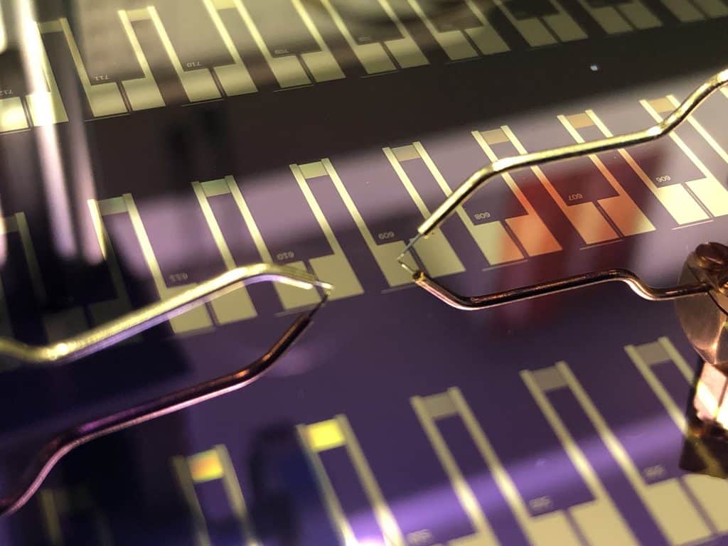
Fingers can be made from different metals and are electrically isolated from each other electrically. High-quality IDEs have high resolution, low noise and can operate at high frequencies. For these reasons, IDEs are used in devices such as pressure sensors, strain sensors and RFID readers.
For example, an IDE coated with a polymer may be used as a strain gauge. When the electrodes are pulled apart, this causes the capacitance of the polymer to increase, which can then be correlated to the distance between the fingers of the IDE.
Capacitance, Resistance, and Impedance
An IDE can be modeled as a circuit containing a resistor and a capacitor in series, and measurements of the electrical properties of IDEs can be performed with either a high-precision LCR meter or a humble multimeter.
Key parameters that identify the performance of an IDE include capacitance, resistance and impedance. In an ideal case, these parameters depend only on the properties of the material deposited between the fingers of the IDE.
Capacitance is a measure of the charges stored in the material between the fingers of the IDEs, while the resistance indicates the amount of energy dissipated when electrical current flows through the IDE. Similar to the resistance, the impedance measures the opposition to alternating (e.g. sinusoidal) electrical current flows.
Impedance and resistance have units of ohms (Ω), while capacitance is measured in picofarads (pF).
The impedance of an IDE is measured by applying an oscillating voltage, at a set frequency, between the two sets of fingers and measuring the resulting current flowing through the device. The measured impedance will depend on the frequency, so it is important to choose a frequency range that is relevant to the application where the IDE will be used.
In contrast, the resistance and the capacitance of an IDE vary little across different frequencies, so these measurements can be performed with a standard multimeter.
Conclusion
To summarize, this article discussed important quantities that can be used to characterize IDEs, including resistance, capacitance and impedance. Platypus Technologies fabricates custom interdigitated electrodes for your application. Typical projects include IDEs made of gold, silver platinum or aluminum on substrates such as glass, silicon wafers, and flexible plastics. Our company also owns and operates a high-precision LCR meter that can be used to measure important electrical properties of IDEs at various frequencies.